H1 Compliance Calculator

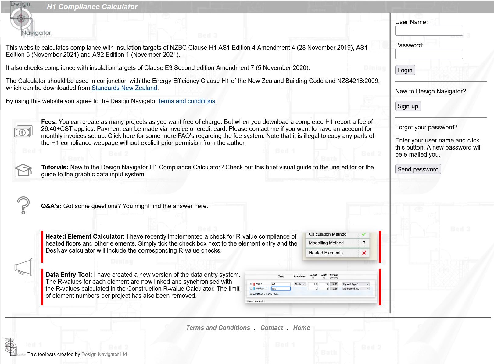
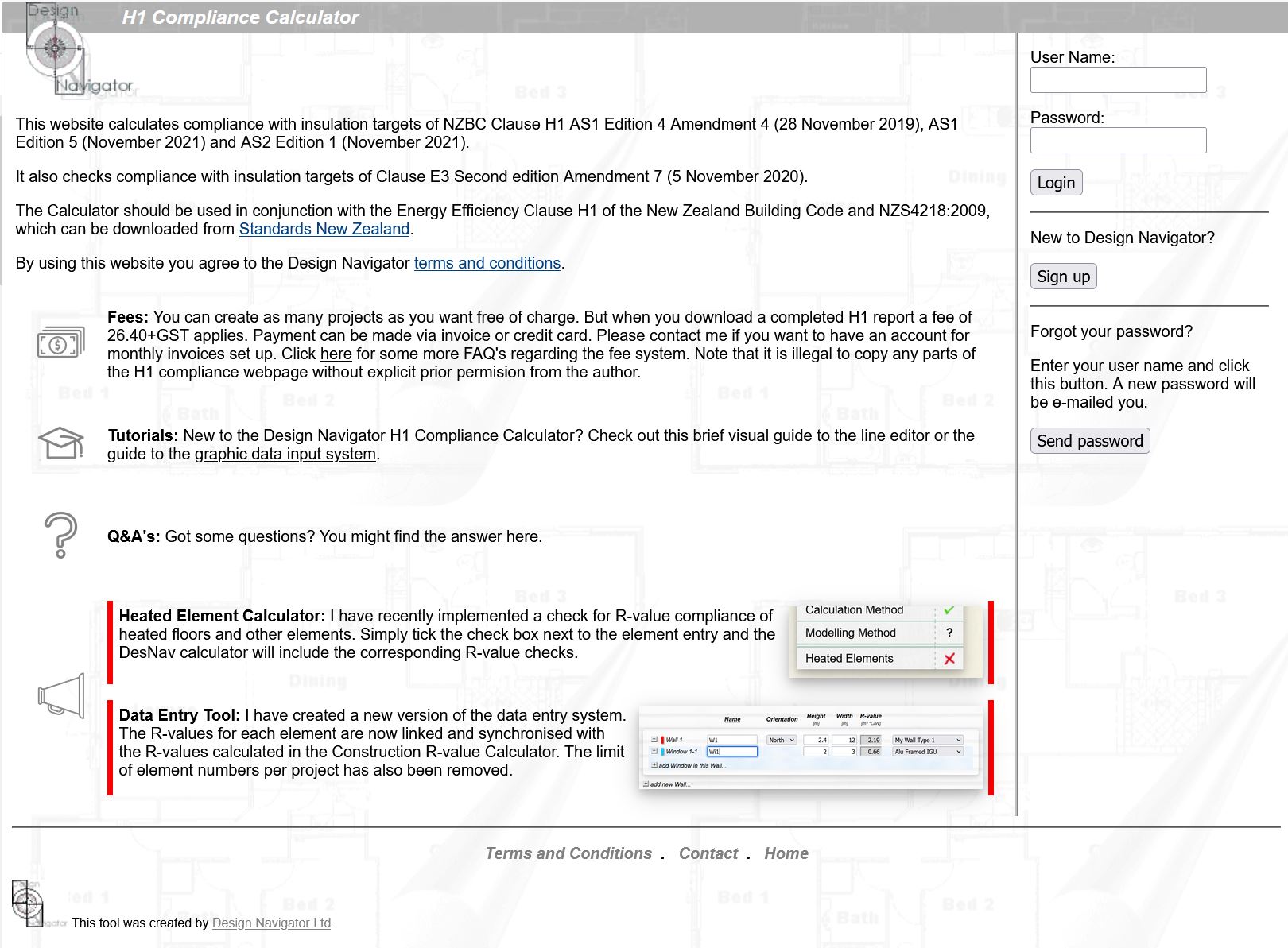
This website calculates compliance with insulation targets of NZBC Clause H1 AS1 Edition 4 Amendment 4 (28 November 2019), AS1 Edition 5 Amendment 1 (August 2022) and AS2 Edition 1 Amendment 1 (August 2022).

It also checks compliance with insulation targets of Clause E3 Second edition Amendment 7 (5 November 2020).

The Calculator should be used in conjunction with the Energy Efficiency Clause H1 of the New Zealand Building Code.

By using this website you agree to the Design Navigator terms and conditions.

Skylight and Door Products

You now have a range of skylight products from Solatube, Velux and Adlux, as well as some Hallmark doors in the DesNav system to choose from.

Automatic R-value for Existing Elements in Alterations

It can be confusing to select the appropriate R-values for existing elements in building alterations and additions. I have therefore automated the process. Depending on the climate zone, the building type, the H1 version and the floor type (slab or other) DesNav will automatically pick the correct default R-value to show compliance in accordance with Section 112 of the Building Act.

Vicinity Alert in the Graphic Entry System

A smart vicinity alert system in the graphic data entry tool highlights locations where elements are closer than 0.5m of each other. This makes element drawings more precise which will be important when the H1 Modelling Method (H1/VM1) will be implemented in the DesNav H1 calculator.

Fees: You can create as many projects as you want free of charge. But when you download a completed H1 report a fee of 26.40+GST applies. Payment can be made via invoice or credit card. Please contact me if you want to have an account for monthly invoices set up. Click here for some more FAQ's regarding the fee system. Note that it is illegal to copy any parts of the H1 compliance webpage without explicit prior permision from the author.

Tutorials: New to the Design Navigator H1 Compliance Calculator? Check out this brief visual guide to the table editor or the guide to the graphic data input system.

Q&A's: Got some questions? You might find the answer here.

Technical:

User Name:

Password:


New to Design Navigator?


Forgot your password?

Enter your user name and click this button. A new password will be e-mailed you.


Home This tool was created by Design Navigator Ltd.
Design Navigator User Guide
Table Editor

1. Open the H1 Calculator

Open the H1 calculator link

2. Sign up

Sign up to the H1 calculator if you haven't already done so. There is no fee to sign up.
Enter your details here. The completed H1 reports and invoices will be sent to this e-mail address.

You can enter multiple e-mails separated by a semicolon.

3. Log in

Here you can find answers to some commonly asked questions.
Use your user name and password to log in.
If you forgot your password you can click here. A new randomly generated password will be sent to the e-mail address in your profile. It is therefore important to keep the e-mail address in your profile up to date.

4. Create a new project

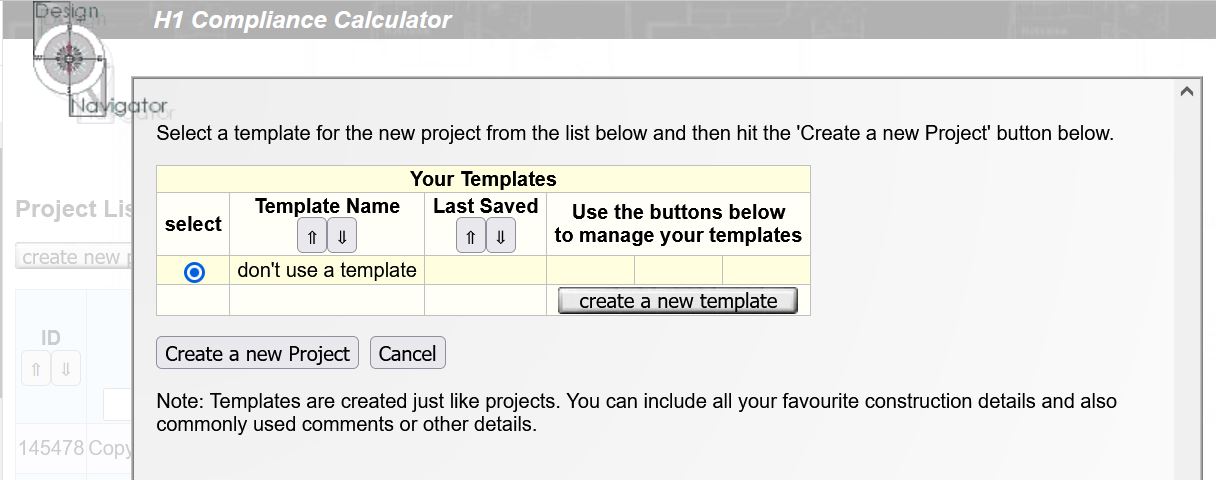
Click here to create a new project.
Here you can create templates which you can use for any future projects.

5. Enter the project details

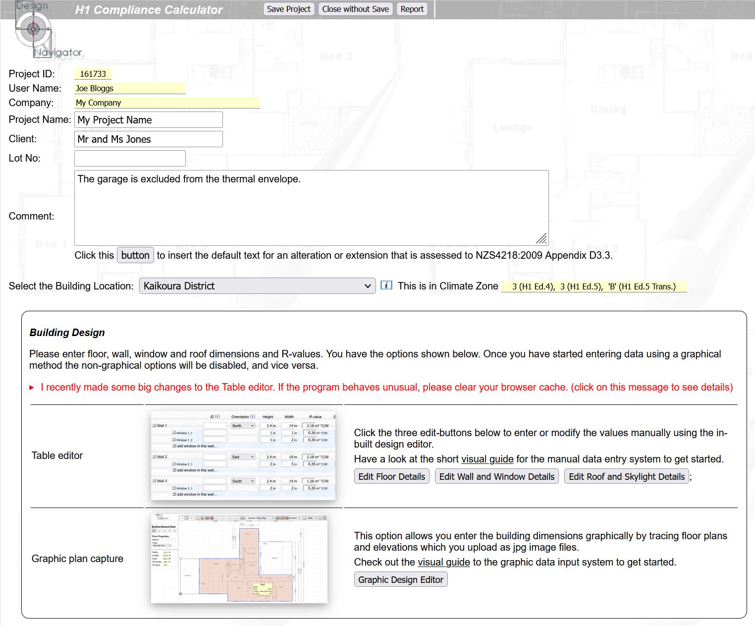
Hover with your mouse over the small blue information buttons to view a short help screen about the item.
Select the correct location. For most compliance calculations the building site just needs to be in the same climate zone.
I regularly add new features to the tool. It is sometimes necessary to refresh your browser cache to make sure everything is working correctly.
Pick one of the data entry methods. Most users prefer the "Table editor". This guide deals with this method.

If you do many H1 calculations it may be worth while getting up to speed with the "Graphic plan capture".
Use these buttons to open the data entry screens where you can enter dimensions and R-values.

6. Enter the dimensions and R-values

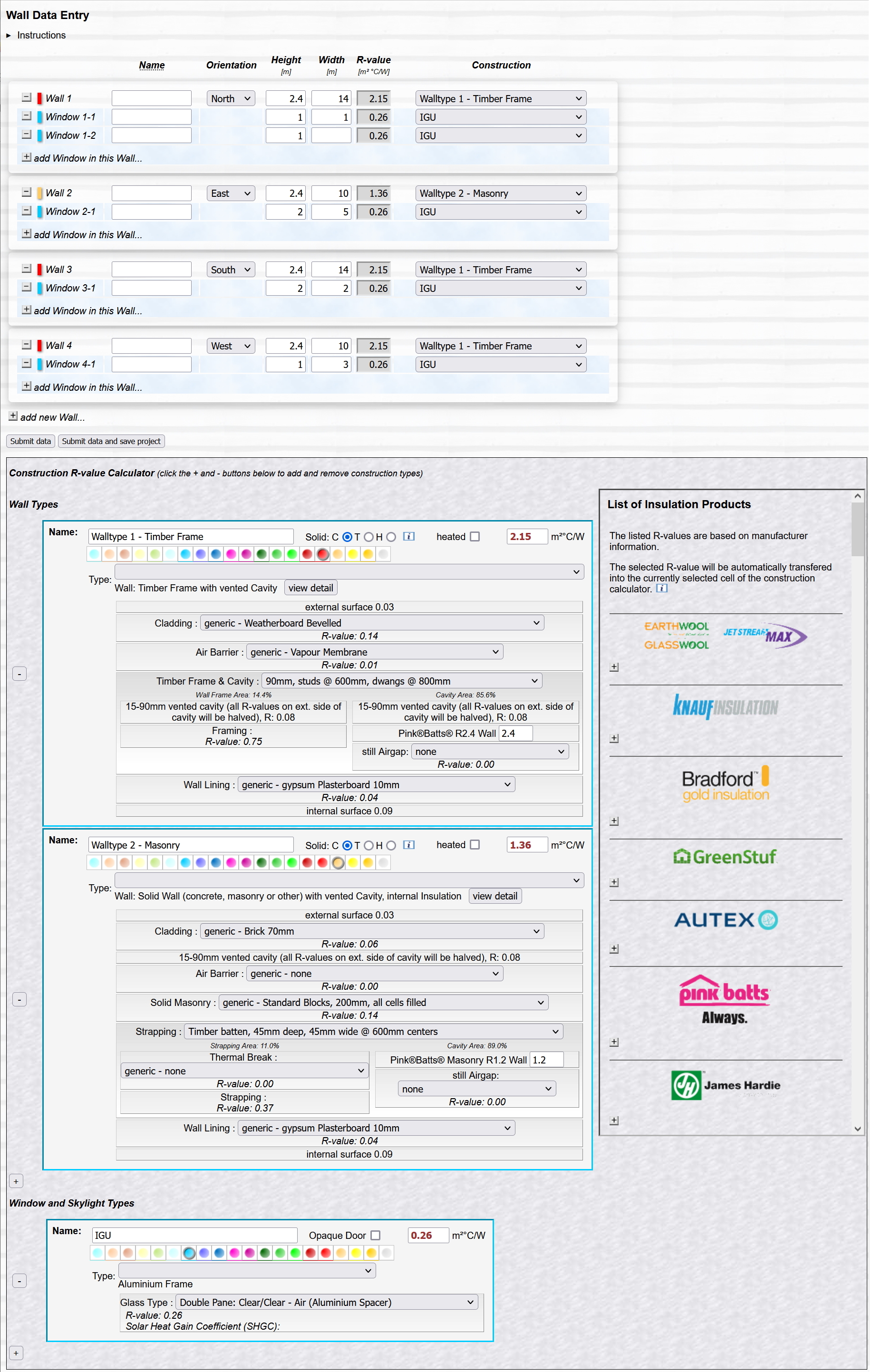
Click on "Instructions" for some tips on how to fill in this page.
Add and remove walls and windows by clicking on the small + and - buttons on the far left.

Enter the orientation and dimension for each wall and window.

Select one of the constructions that you have created in the Construction R-value calculator section at the bottom of the screen. The R-values are automatically copied into the element and are kept synchronised with the Construction R-value Calculator.
Use this lower section to calculate the construction R-values.

Add and remove constructions using the small + and - buttons on the left.

Also choose any special element features in this section, such as heated elements, solid walls, roof perimeters, etc.
Once you finished entering all your data click on one of the 'submit' buttons. This will close this screen and send the data to the main screen where it will be included in the H1 calculations.

You can also hit CTRL "s" for submitting the data and saving the project.

7. Pick a suitable Acceptable Solution and check for compliance

Pick one of the Acceptabe Solutions to check for compliance.

Note that some outdated options are still available so that you can re-assess existing projects which were consented under old rules.
This table gives you an overview of the design details you have entered.

It also shows the glazing percentages and whether the design meets the other preconditions that are required to use certain compliance method.
Some compliance methods can only be used if the design meets certain conditions, such as having less that 30% glazing area. This section shows which of the compliance methods can be used.

Hover over underlined items to display the reasons why a method can or can't be used.
This section shows whether the the design complies with the Schedule Method. Red crosses mean that your proposed lowest R-value doesn't meet that target.
This section shows compliance with the Calculation Method. Both the heat loss target and the individual 50% R-value targets must be met.

The chart helps you to prioritise any required improvements. In this example much of the heat is lost through the floor. So the floors would be the place where insulation improvements would be most effective.
Any heated elements must also comply with individual R-value targets. These cannot be reduce by trading them off against higher R-values in other elements.

There are checkboxes next to each Construction R-value on the data entry screens which allow you to specify whether the element is heated or not.
This section shows whether the design complies with Clause H1. The design needs to comply with only one of the methods.

But if it has any heated elements these must always comply with the heated element R-value targets.
Here you see whether the design complies with the R-value targets in Clause E3.
If you are interested whether your design meets the thermal requirements for a Homestar rating you can complete this section. If you buy an H1 report for this project you can also download a Homestar report free of charge.

The thermal performance is only one of the Homestar criteria. The design must also meet other sustainability requirements to achieve a Homestar rating. These are not part of the Design Navigator tool.

8. Get your H1 report

Click on the buttons at the top of the screen to save your project and to generate a report.
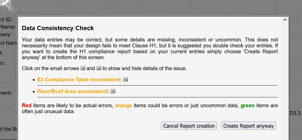
If there are any inconsistencies in your data this screen will appear. Click on the small buttons next to each issue to view more details about the issue.
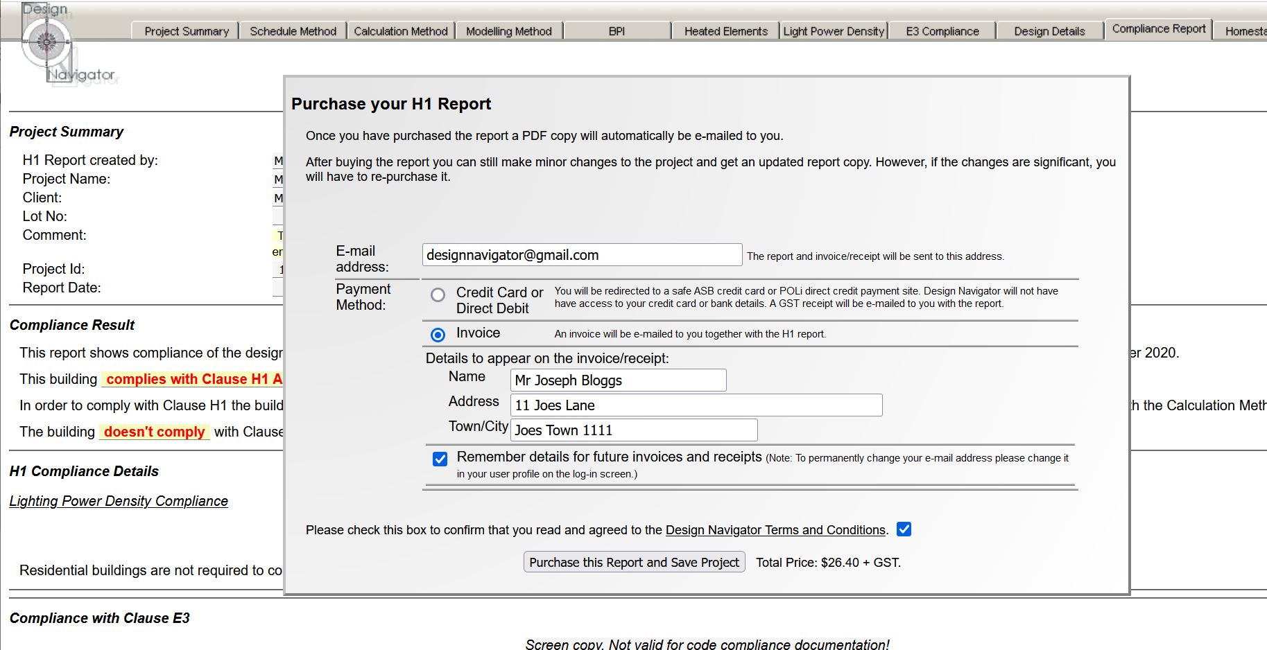
Open the 'Compliance Report' tab and select your preferred payment option. Click the ''Purchase this Report' button. The report and payment document (invoice or tax receipt) will be e-mailed to the e-mail address entered above.

If you need to make changes to the project you can do that even after you bought the report. Simply re-open the project, make your changes and get another report. The system will know that you already bought a report for the project and will not ask for payment again.
Any questions? Please just drop me an e-mail at designnavigator@gmail.com.

Design Navigator User Guide
Graphic Editor

1. Open the H1 Calculator

Open the H1 calculator link

2. Sign up

Sign up to the H1 calculator if you haven't already done so. There is no fee to sign up.
Enter your details here. The completed H1 reports and invoices will be sent to this e-mail address.

You can enter multiple e-mails separated by a semicolon.

3. Log in

Here you can find answers to some commonly asked questions.
Use your user name and password to log in.
If you forgot your password you can click here. A new randomly generated password will be sent to the e-mail address in your profile. It is therefore important to keep the e-mail address in your profile up to date.

4. Create a new project

Click here to create a new project.
Here you can create templates which you can use for any future projects.

5. Enter the project details

Hover with your mouse over the small blue information buttons to view a short help screen about the item.
Select the correct location. For most compliance calculations the building site just needs to be in the same climate zone.
I regularly add new features to the tool. It is sometimes necessary to refresh your browser cache to make sure everything is working correctly.
Pick one of the data entry methods. Most users prefer the "Table editor" for its simplicity, but if you do many H1 calculations or if the design is quite complex it may be worth while getting up to speed with the "Graphic plan capture".

This guide deals with the Graphic plan capture.
Use these buttons to open the Graphic plan capture screens where you can enter dimensions and R-values.

6. Choose between plan and elevation data entry

Choose which way you plan to enter the wall and window dimensions.

The Plan View option allows you to trace the floor plans and manually enter the wall and window heights.

The Elevation View allows you to enter the wall and window dimensions by tracing elevations.

Note that you cannot use both options simultaneously in one project. Once you have made a selection you are not able to convert one method into another.

It is usually easier to use the Plan View method, in particular if you create the report for a project you designed yourself and know the wall and window heights by heart.

7. Define the construction details

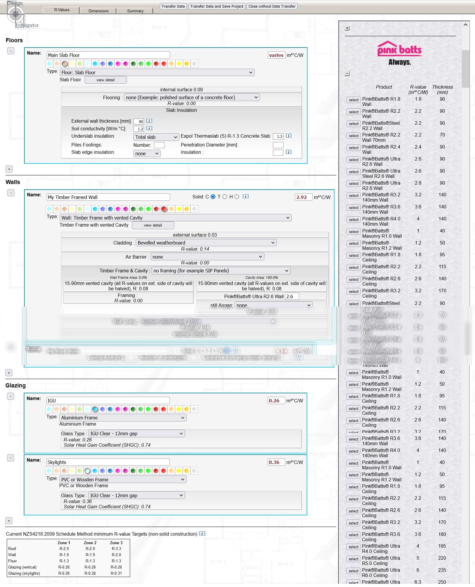
Enter the details of your constructions on the "R-Values" page. This calculates the construction R-values and allows you to assign the details to the elements on your drawings.
Note that alternatively you can first complete the drawings on the "Dimensions" page and later create and apply the construction types.
Select a colour for this construction type. This allows you to quickly identify the construction type in your drawings.
Enter a construction name. These names will be used to assign constructions to the building elements on your drawings.
For walls you can select whether it is a cavity construction, a solid timber construction or a heavy mass construction. The different wall types have different compliance targets.
Remember to also create constructions for elements for which you do know the R-value, like for example for double glazing. Otherwise you could not assign the detail in your drawings.

8. Load a floor plan

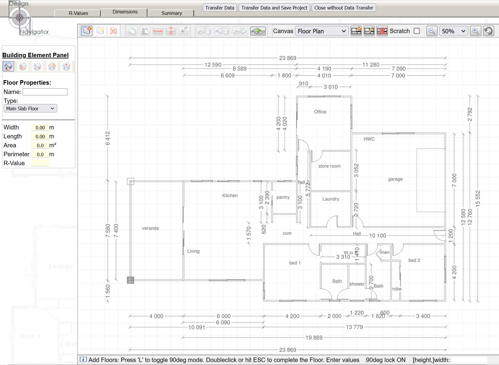
On the "Dimensions" page you load and trace your floor plans. You can create multiple canvases one for each floor level in multi-level designs.

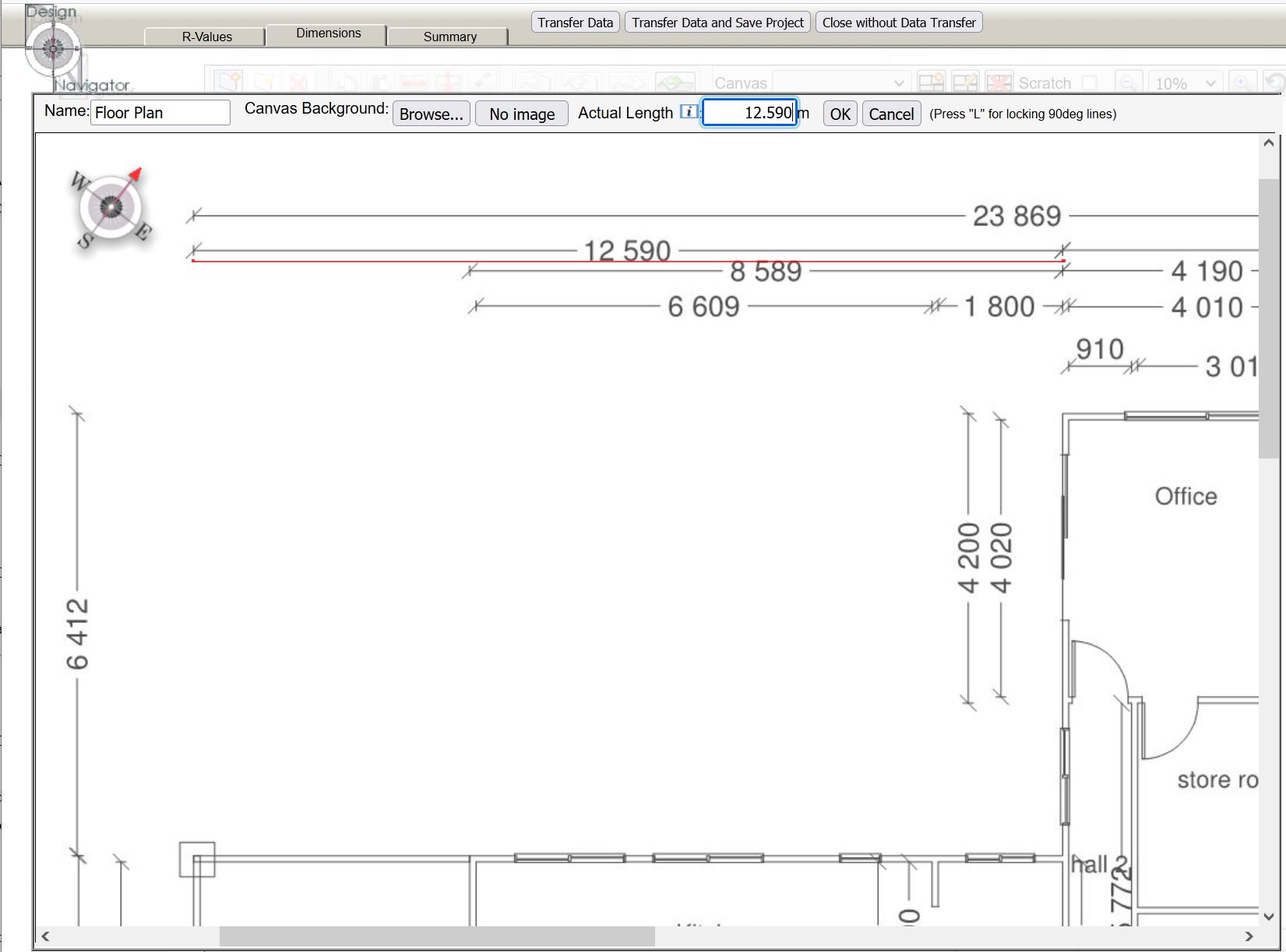
Give your drawing a name and browse for the image file on your computer. You can upload a number of image formats, but no PDF files. If your design software does not allow you to export image files you can either screenshot your plans or use one of several free conversion programs on the internet. The conversion programs have the advantage that all your image files will have the same scale and the reference lines for multiple floor levels will be consistent between the images if they are consistent in the pages of your drawings.
In order for the program to correctly scale your drawings adjust the red line to have the same size as a dimension line on your plan. Pick and drag the ends of the red line to adjust its size. Hitting the "L" key will lock and unlock the line from drawing in 90deg angles. The accuracy of the scale will be better if you match long dimension lines rather than short ones. Once the reference line matches the size of the plan's dimension line enter the corresponding length in the "Actual Length" box. You can enter simple formulas if the reference line matches multiple adjacent lines on your floor plan, for example "0.09+3.5+0.09+2.7+0.09".

Once you entered the dimension rotate the compass in the left upper corner by dragging the red arrow point to match the plan's orientation. This will allow the program to assess the window percentages facing each of the main compass points.

9. Plan tracing overview

Use these five buttons to switch between the element types: Floors, walls, windows, roofs and skylights.
You can name individual elements so that they can be easier identified in the report.
The "Type" drop-down box lists the construction types which you have created on the "R-values" page. It allows you to assign constructions to your elements.
For walls and windows you also enter the element height here.
The buttons in the top bar give you access to various tools for editing your drawings. Hover over the buttons to see small pop-up hints explaining their functions.
Note in particular the transfer buttons which allow you to quickly transfer a floor outline into walls or the roof.
Create, edit and delete elements.
Copy, paste and manipulate elements.
Transfer outlines of one element type into another.
Select, add, edit and delete the canvass. Check "Scratch" to exclude the canvass from the calculations.
Zoom in and out. Scroll the mouse wheel for quick zooming.
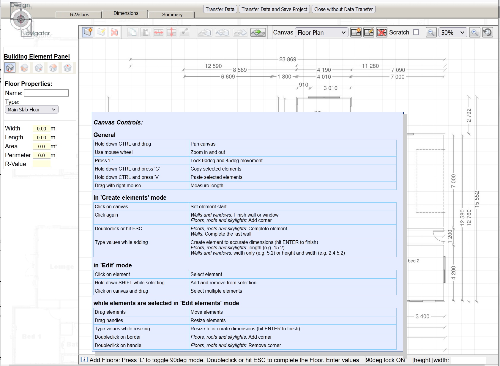
There are a number of shortcuts you can use. Hover over the small blue information icon to see what they are.
Type a number while in "create" or "edit" mode and hit enter to make the element a specific size. Type one number to specify the width. Type two numbers separated by a comma to specify height and width. The typed numbers are shown in the box in the bottom right corner.
Note that the program remembers the last entered height. To enter subsequent walls or windows of the same height start drawing, then type the width and hit enter.

10. Draw the building elements

Create Floors

Select the "Floor" button and the correct construction type from the "Type" drop-down box on the "Building Element Panel" on the left. Click on the leftmost button in the tool panel on the top ("create element").
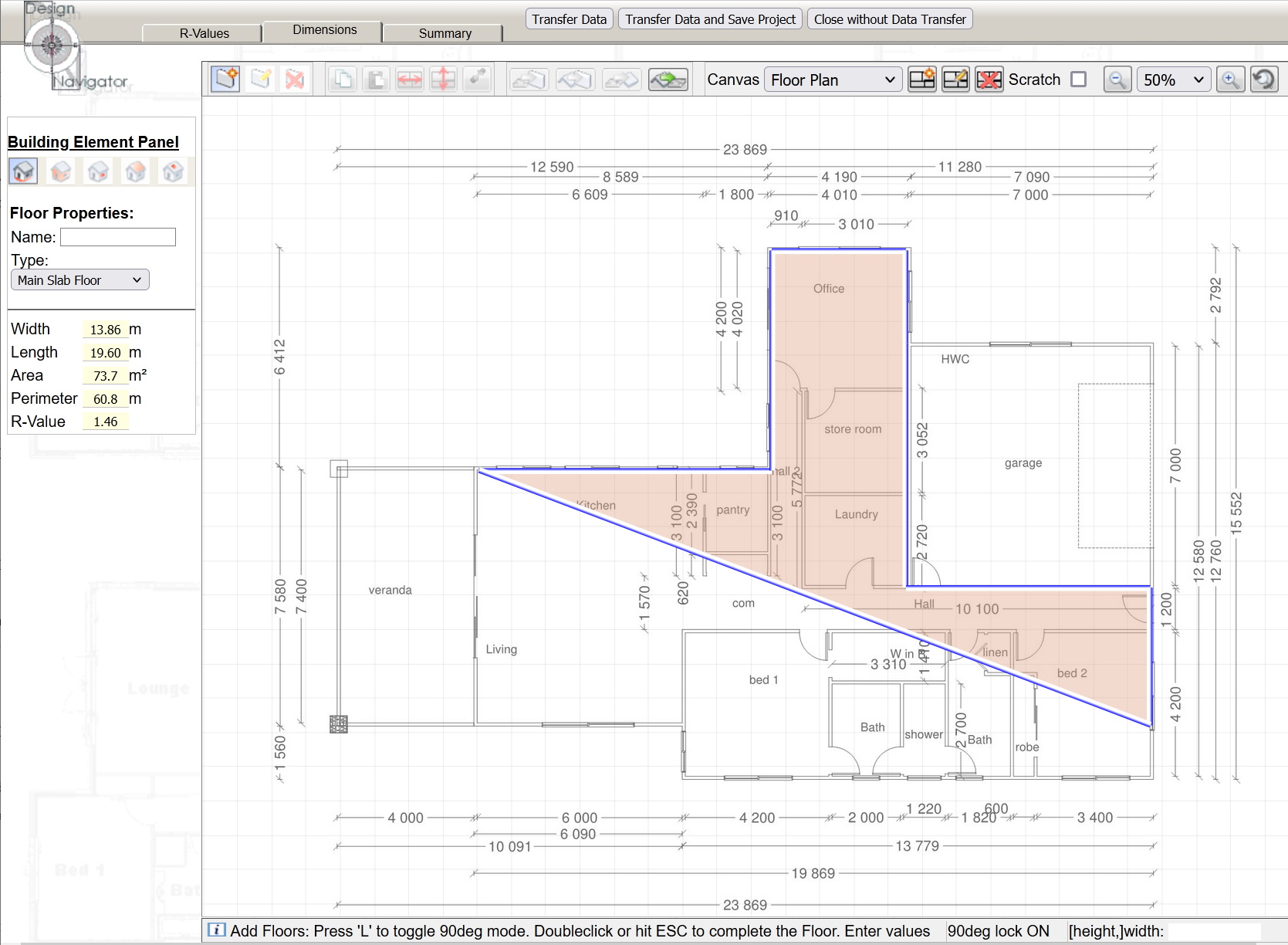
Then start drawing the floor by clicking on a corner and moving the mouse. To draw in 90deg and 45deg angles hit the "L" key. Click to create a corner. After you clicked on the last corner hit the ESC button to complete the floor.
While you are drawing the covered floor area is shown in the colour you have selected on the "R-Values" page for that construction type. When drawing complex layouts the covered area may look confusing and temporary show covered areas outside the floor and vice versa. But once you completed the outline the areas will match.
Remember to draw around the floor clockwise. This will make sure that if you later transfer the floor outline to walls that the walls have the correct orientation. Add vertices (i.e. click) also where wall types change, even if this is along a straight floor edge. That way you will automatically create two separate walls along that edge when you transfer the outline into walls and you can then easily assign the respective construction details to those separate walls.
NZS4218 suggests to use the internal dimensions of elements when doing H1 calculations.

Edit Floors

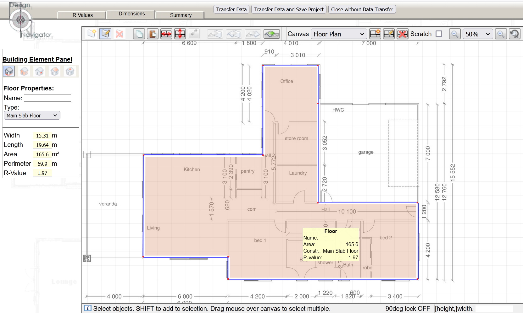
Once you completed the floor you can edit it by clicking on the "edit element" button.
Click on the floor to select it. The panel on the left will show the details of the floor. There you can also change the floor construction type by selecting it from the drop down list.
Hold down the SHIFT key to select multiple elements or click outside the elements and drag the appearing frame across the elements you want to select.
Click and drag the corner poins to change the floor outline. Remember that hitting the "L" key will turn the 90/45deg lock on and off.
Double click on the edge to create a new corner point.
Double click on a corner point to remove it.
When you hover over the floor a small pop-up window will show the element details including its R-value, which in the case of floors depends on both the floor area and the floor perimeter.

Create Walls

When the floors are complete enter the walls.
Click on the wall button in the left panel to switch to wall mode.
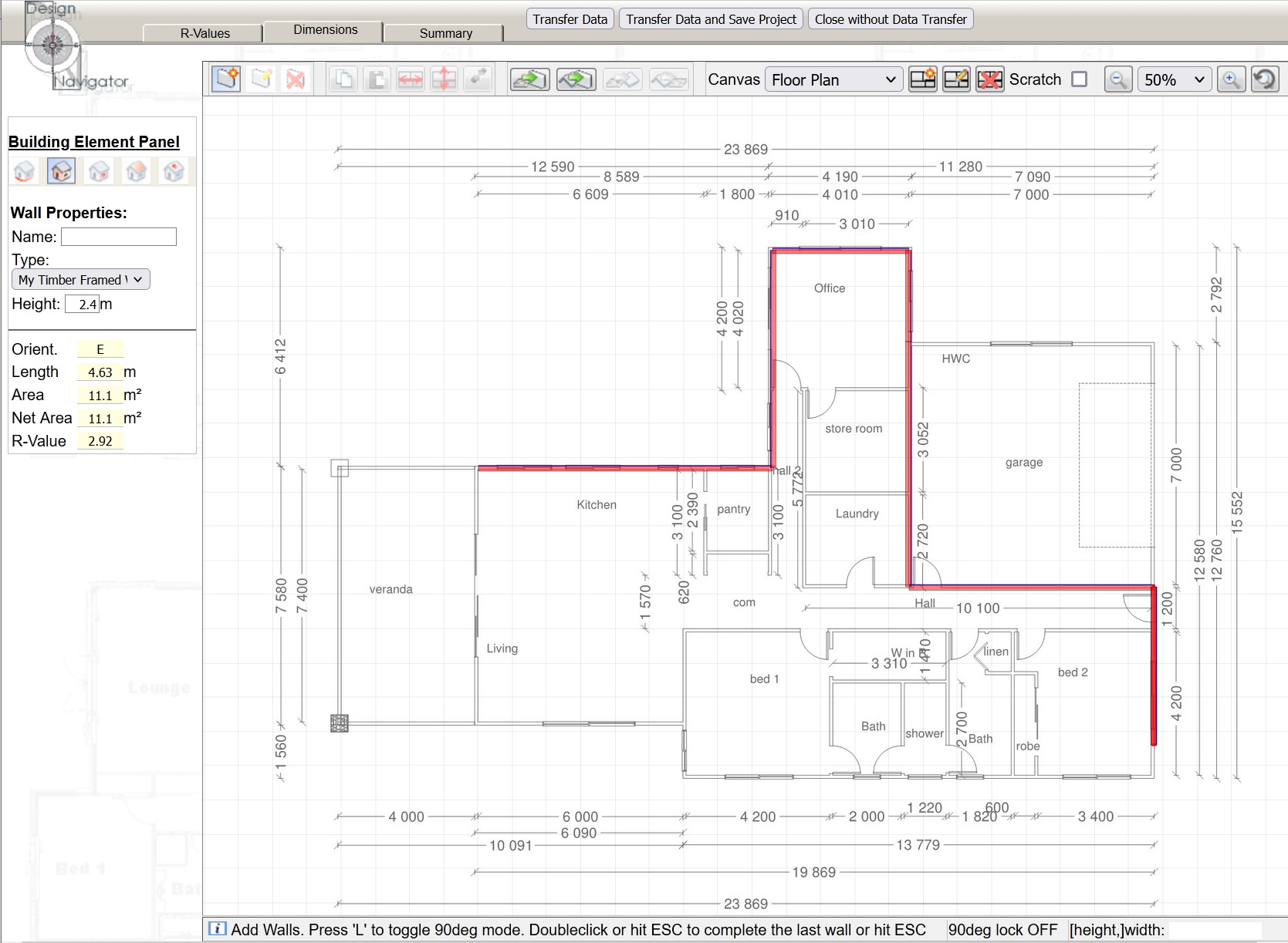
You can draw the walls in the same way as you have drawn the floor. However, a shortcut is to simply click on the "transfer button" in the top panel. That will create walls along all of the floor edges.
If you have multiple floors there may be duplicate walls where the floors join. Simply remove those walls by selecting them and hitting the DELETE key or select the "delete element" button in the top panel and then click on the walls you want to delete.
Note that there is currently no "undo" button the the DesNav calculator!

Edit Walls

To edit the walls select the wall button in the left panel and the "edit element" button in the top panel.
Select the walls you want to edit. Then change their heights and construction types in the left panel. The colors of the walls will update to the colors you have selected for the wall construction which you created in the "R-values" tab.
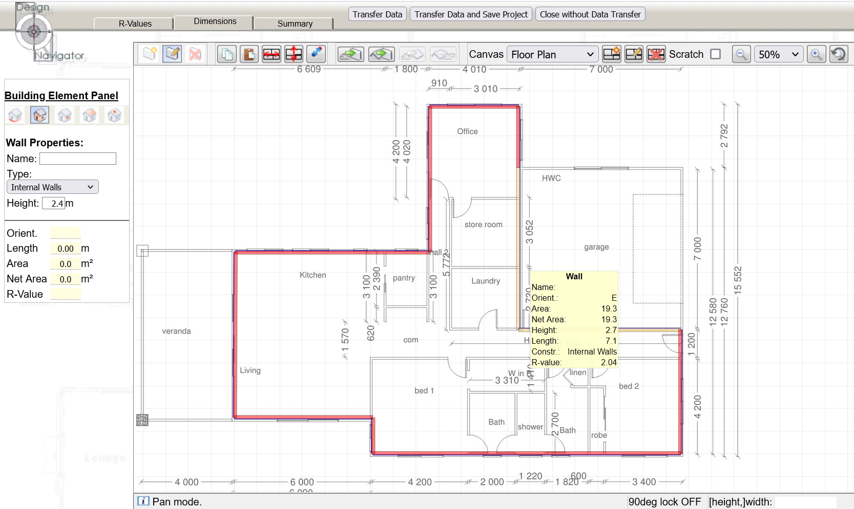
As with the floors you can hover over the walls while in "element edit" mode to see a pop-up with the wall properties. This is particularly useful to quickly check the wall heights.
The wall orientations should be correct if you have drawn the walls in a clockwise fashion. If you have to change them you can use the "swap inside out" button in the top panel.

Add Windows

To create windows select the window button in the left panel and the "create element" button in the top panel.
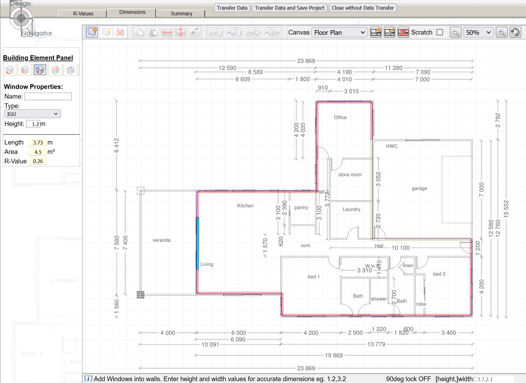
Enter the window height in the left panel and select the correct construction type from the drop down list. Then click on the wall where you want to create the window. Move the cursor along until the window has the correct length. Click again to complete the window.
The window will automatically have the same orientation as the wall irrespective of whether you draw it clockwise or counterclockwise.
The window type and height will remain selected in the left panel. So it can be efficient to draw all the windows of the same height and type after each other. Then change the height and type in the left panel and draw the next set of windows, etc.
Because windows have comparatively low R-values it is more important to get the dimensions correct than for other building elements. It can therefore be useful to use the "typed dimension" feature.
In order to do that click on the location on the wall and start drawing the window. This will tell the program which way along the wall the window should be drawn. But instead of clicking where the window finishes type the length of the window and hit ENTER.
Alternatively you can also type both the height and the length separated by a comma and then hit ENTER.
The typed values are shown in the textbox at the right bottom corner of the canvas.

Add Elevation Drawings

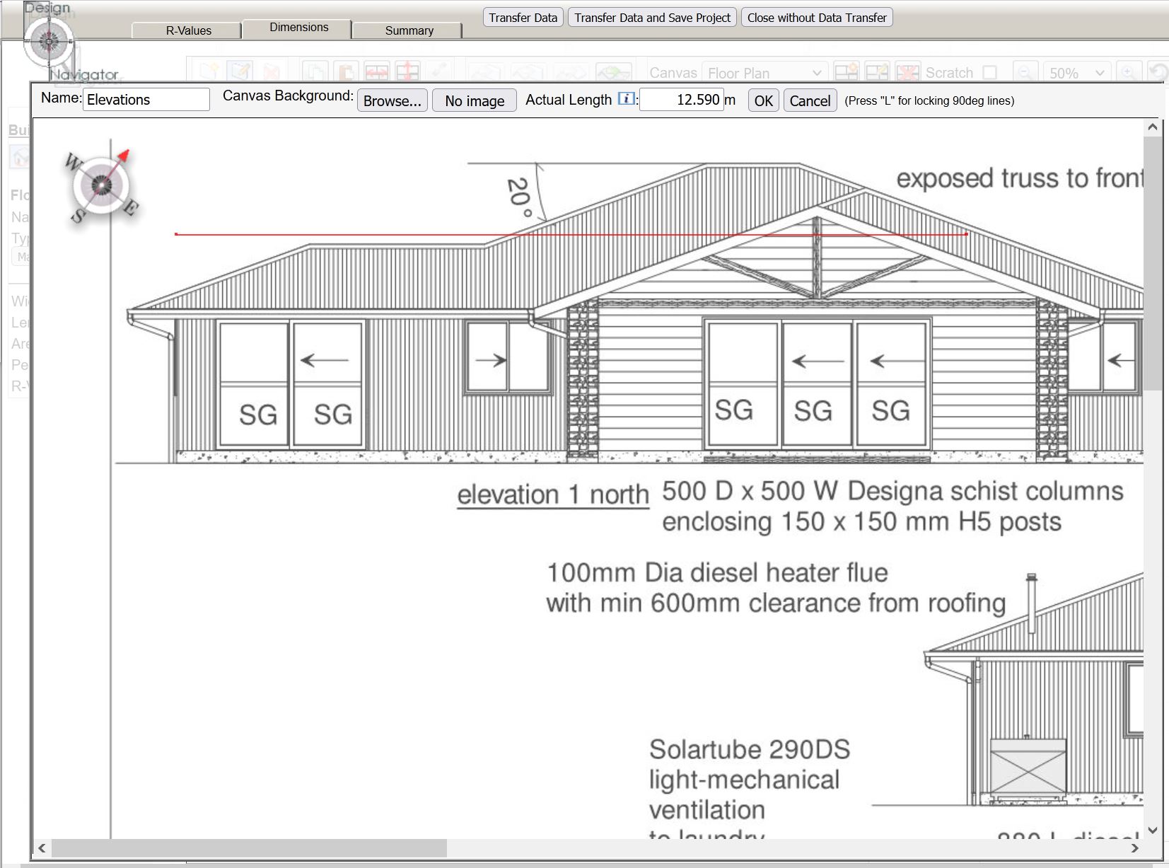
While in "edit element" mode when you click the right mouse button and drag along the canvas a small pop-up will show the length of the line. It can therefore sometimes be useful to add also elevation drawings into the project. You do that the same way as you add the plans. It is important that the elevations are also scaled correctly, however, in that case you can ignore the orientation compass.
Note that if you add all the plan and elevation views in one go the red scaling line will be preserved. Assuming that the original image files have the same scale you don't have to redraw the red scaling line and enter the actual dimensions.

11. The Summary Page

The summary page has two particularly useful features.
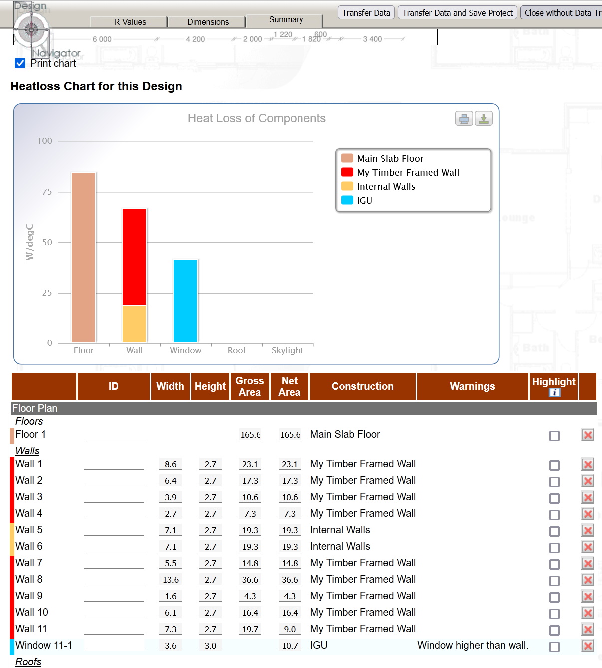
The graph shows you the heat loss of of your elements. This can be useful if you don't meet the compliance targets, because it allows you to prioritise any R-value improvements. In this particular hypothetical example most of the heatloss occurs through the floor. This would therefore be the most effective place to improve the insulation.
The table at the bottom lists all your elements. If any of the elements have inconsistent or unusual dimensions they are flagged.
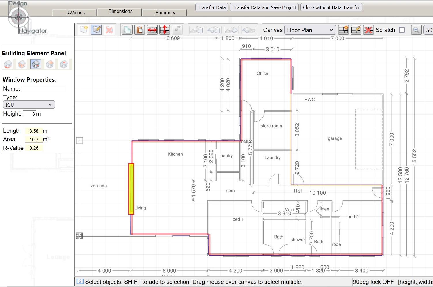
Click on the checkbox next to the element and go back to the "Dimension" page. The element in question will be highlighted in yellow. (see below...)
The red delete button allows you to delete elements. This can be useful if by accident you have drawn elements with no lengths or width because they can be hard to spot on the canvas.
Make sure that the "Dimensions" page shows the correct canvas and element type.
When you click on the element the yellow box will disappear and you can correct the element properties.

12. Save and Submit

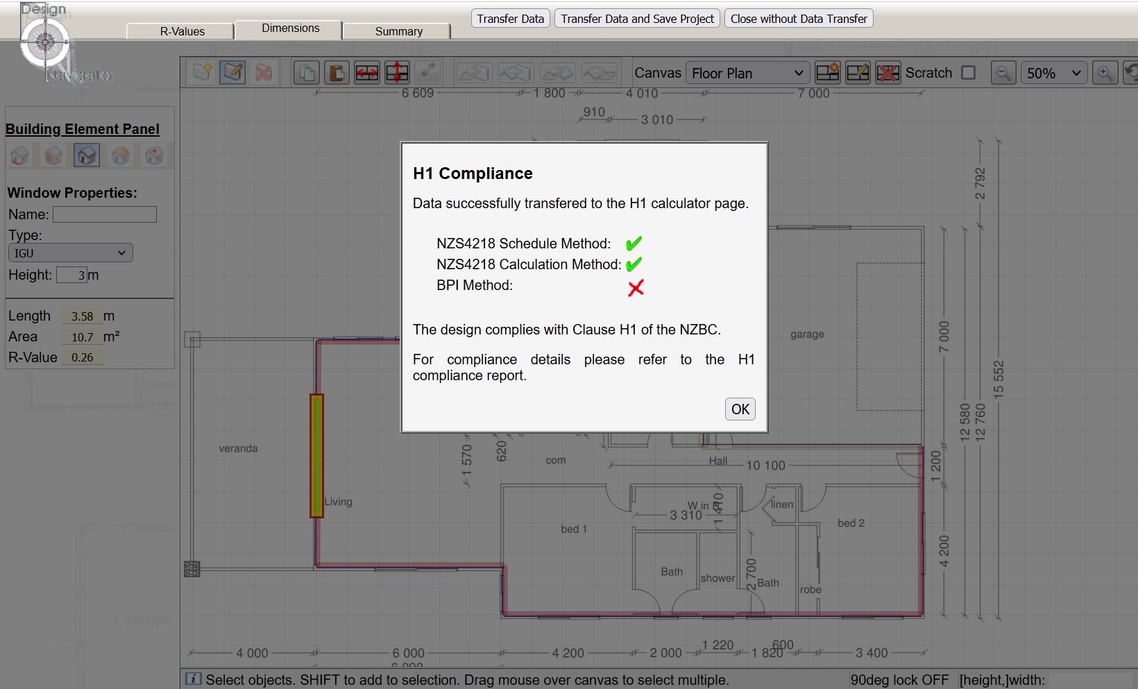
Finally transfer the data to the main H1 calculator page and save the project.
The calculator will run the H1 compliance calculation and show the results. To check the reasons why it may not comply with any of the three compliance options go to the report page ("Report" button in the header of the main H1 calculator page) and check the compliance details.

13. Pick a suitable Acceptable Solution and check for compliance

Pick one of the Acceptabe Solutions to check for compliance.

Note that some outdated options are still available so that you can re-assess existing projects which were consented under old rules.
This table gives you an overview of the design details you have entered.

It also shows the glazing percentages and whether the design meets the other preconditions that are required to use certain compliance method.
Some compliance methods can only be used if the design meets certain conditions, such as having less that 30% glazing area. This section shows which of the compliance methods can be used.

Hover over underlined items to display the reasons why a method can or can't be used.
This section shows whether the the design complies with the Schedule Method. Red crosses mean that your proposed lowest R-value doesn't meet that target.
This section shows compliance with the Calculation Method. Both the heat loss target and the individual 50% R-value targets must be met.

The chart helps you to prioritise any required improvements. In this example much of the heat is lost through the floor. So the floors would be the place where insulation improvements would be most effective.
Any heated elements must also comply with individual R-value targets. These cannot be reduce by trading them off against higher R-values in other elements.

There are checkboxes next to each Construction R-value on the data entry screens which allow you to specify whether the element is heated or not.
This section shows whether the design complies with Clause H1. The design needs to comply with only one of the methods.

But if it has any heated elements these must always comply with the heated element R-value targets.
Here you see whether the design complies with the R-value targets in Clause E3.
If you are interested whether your design meets the thermal requirements for a Homestar rating you can complete this section. If you buy an H1 report for this project you can also download a Homestar report free of charge.

The thermal performance is only one of the Homestar criteria. The design must also meet other sustainability requirements to achieve a Homestar rating. These are not part of the Design Navigator tool.

14. Get your H1 report

Click on the buttons at the top of the screen to save your project and to generate a report.
If there are any inconsistencies in your data this screen will appear. Click on the small buttons next to each issue to view more details about the issue.
Open the 'Compliance Report' tab and select your preferred payment option. Click the ''Purchase this Report' button. The report and payment document (invoice or tax receipt) will be e-mailed to the e-mail address entered above.

If you need to make changes to the project you can do that even after you bought the report. Simply re-open the project, make your changes and get another report. The system will know that you already bought a report for the project and will not ask for payment again.

Any questions? Please just drop me an e-mail at designnavigator@gmail.com.

FAQs

Does the building have to comply with Clause H1?

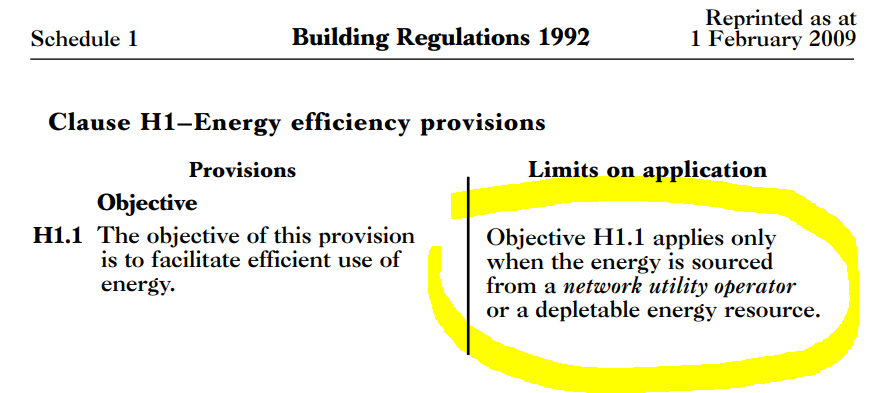
The very first thing to check is whether the building is going to utilise energy from a network utility operator or uses any depletable energy sources. This is usually the case, but it would exclude for example a lifestyle home that has it's own solar power panels for electricity and uses firewood for space and water heating. But as soon as it would use LPG gas for example the exemption wouldn't apply because LPG is depletable.
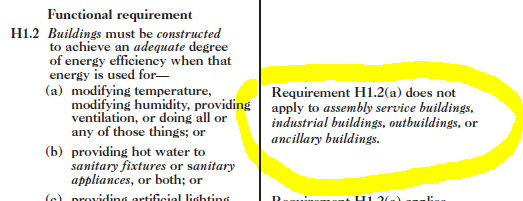
The next step to check is whether the building falls in one of the building classifications that do have to comply with the thermal requirements of H1.2(a). Specifically assembly service buildings, industrial buildings, outbuildings, and ancillary buildings do not have to comply with the thermal requirements of Clause H1. The screen shot below shows the relevant section in Clause H1.
A description of the classified uses with some examples is in Schedule 1 of the Building Code.

If the building does not fall into one of these groups then you have to comply with the thermal section of Clause H1. In that case the permitted compliance method depends on the building size and type.

Which compliance methods apply to my building?
All housing,
and
all buildings up to 300m²
Buildings larger than 300m²
Typical examples:
  • a "typical" house that is smaller than 300m²
  • a large apartment building bigger than 300m²
  • a small office which is smaller than 300m²
Typical examples:
  • a large office building
  • a large school building
  • a library
until 2 November 2022:
  1. AS1 Edition 4 (2019) - thermal (NZS4218:2009)
  2. AS1 Edition 5 (2021) - thermal *
  3. VM1 Edition 5 (2021) - thermal *
  1. AS1 Edition 4 (2019) - thermal and lighting (NZS4243:2007 or NZS4218:2009)
  2. AS2 Edition 1 (2021) - thermal and lighting
  3. VM2 Edition 1 (2021) - thermal and lighting
from 3 November 2022:
  1. AS1 Edition 5 (2021) - thermal
  2. VM1 Edition 5 (2021) - thermal
  1. AS2 Edition 1 (2021) - thermal and lighting
  2. VM2 Edition 1 (2021) - thermal and lighting
  3. VM3 Edition 1 (2021) - HVAC systems
* For housing AS1 and VM1 Edition 5 has a transition period until 30 April 2023 during which the R-values targets for floors, walls, roofs and windows are reduced. This transition period ends on 1 May 2023. The transition period does not apply to buildings of any size which are not housing.

All of the Acceptable Solutions (AS1 Edition 4, AS1 Edition 5 and AS2 Edition 1) include a Schedule Method and a Calculation Method. The Schedule Method is a simple lookup table of R-values that your design has to meet. The Calculation Method allows some trade-offs between R-values in one element agains those in another. For example you can drop the roof insulation if you increase the wall insulation, etc. There are some prerequisites for using each of these methods and some additional requirement to meet the compliance requirements whch are specific to each version and edition of the Acceptable Solution. These conditions are all automatically checked within the Design Navigator Calculator. The Design Navigator Calculator also shows on its report pages why the design complies with a certain method or not.

One important thing to remember is that all of the Acceptable Solutions only assess the R-values of the building. They do not assess other thermal features such as solar exposure, thermal mass, internal air flows, etc. Although thermal insulation (R-values) are by far the most important factor for the thermal performance of a building looking at only the R-values can in some cases not give the full picture of a building's thermal performance and comfort.

The Verification Methods (VM1 Edition 4, VM1 Edition 5 and VM2 Edition 1) require a full scale thermal modelling of the building. Such a model simulates the building's heat flows and temperatures on an hour-by-hour scale for a typical climate year taking account the thermal insulation, but also factors such as solar gains (orientation of the building and window sizes), thermal mass, and it may even look at infiltration and ventilation effects. Such a model also looks at different thermal zones within a building. This allows the consideration of different comfort requirements throughtout building, i.e. a living room may be kept at 20degC whereas a bathroom at 16degC. These thermal simulations are reasonably complex and the Design Navigator calculator does therefore not include this assessment method. But I can undertake a Modelling Method assessment for you on a consultancy basis if you are interested.

How do I calculate compliance for additions and alterations?

The new Clause H1 Edition 5 unfortunately doesn't provide any clear guidance on alterations and additions. The Building Act says that if the building did not comply with the provisions of the building code immediately before the building work began, it has to “continue to comply at least to the same extent as it did then comply”. But in regards to energy efficiency performance it is not that clear what “the same extent” means.

If you only replace some building elements and don't change or add any additional elements then you can interpret that to say that you just must not reduce any R-values. But if it involves some additions to the building or other element alterations such as changing window sizes it becomes more complicated.

In those cases I recommend to use the approach that is described in NZS4218:2009 Appendix D. That suggests to assess the whole building, rather than just the new parts. But the trick is that for any existing unchanged parts of the building you can for calculation purposes assume that they have R-values meeting the Schedule Method targets (H1/AS1 Ed.5 Table 2.1.2.2B), irrespective of their actual R-values. Only for any new or changed elements (walls, windows, roofs, floor) you will have to calculate and use their actual construction R-values.

So for example if your existing building has R-1.7 walls, you can still enter R-2.0 for these existing walls in the DesNav calculator, as if they are meeting the current Schedule Method target. Only for those elements that are new or have been modified you enter their actual R-value.

There is a DesNav construction R-value option for these unchanged existing elements. Make sure you select the option for the *current* H1 edition, i.e. the one you are checking for compliance for, rather than the H1 edition when those existing elements were built. So usually you should select one of the H1 Edition 5 options:

Internal elements between the new and the old part of the building are ignored just like normal internal walls, midfloor, etc.

You can only use those “default” R-values for existing parts that were residential and had to comply with H1 before. So if you are for example converting an existing garage into a living space you would need to use the actual garage R-values, meaning that you would probably have to insulate it, in case it wasn’t insulated before.

What is the R-value of slab pod insulation systems?

Pod insulation systems consist of insulation pods (usually polystyrene) placed underneath the slab. Concrete channels separate each pod and provide structural stability.

The R-value of pod insulation systems is quite complex to calculate and the literature is conflicting.

Two relevant references are a BRANZ article published in the BUILD magazine in 2011 (BUILD 123 April/May 2011, page 26) and the Firth RibRaft Design Solution Brochure.

The BRANZ article is based on thermal computer simulations and found that "...for a traditional slab-on-ground floor without insulation ... the thermal resistances of the (pod insulated) floors are similar for a building with 100 mm deep walls." For 250mm deep walls the simulations found an R-value increase of 20% compared to an uninsulated slab.

The Firth Design Guide on the other hand refers to NZS4214:2006 and lists quite significant R-value increases due to the RibRaft system. It should be noted that the referenced Standard does not specifically cover pod insulation systems and only deals with total slab insulation and slab edge insulation.

AS1 Edition 5 includes an extensive list of slab R-values which have been calculated independently without references to NZS4214:2006. These tables also include some scenarios for slabs with pod insulations. The tables have been implemented in the Design Navigator construction R-value options.

These R-values can also be used for designs that show compliance with AS1 Edition 4.

If a particular slab detail for a pod insulation floor is not included in the available options I recommend to use one of the options which don't include the pod insulation because the pods have only a minor impact on the slab R-value.

Can the Design Navigator Calculator be used for commercial buildings?

AS1 Edition 4

In AS1 Edition 4 you have some flexibility. It allow to show compliance for large building using either NZS4243 or NZS4218. NZS4218 is the method that is implemented in the Design Navigator for AS1 Edition 4 compliance.

That means that you can use the Design Navigator calculator to show compliance with Clause H1 AS1 Edition 4 also for a building larger than 300m². If the building fails to comply you can either increase the insulation levels to meet NZS4218 (using the Design Navigator calculator) or instead you check whether it complies with NZS4243 (which is not part of the DesNav calculator).

Note that for some large non-residential buildings you also need to show that the lighting power density complies with Clause H1. Usually your lighting consultant will be able to do these calculations for you.

AS2 Edition 1

Since November 2021 a new Acceptable Solution is available for buildings larger than 300m² that are not housing. This is "AS2 Edition1".

As with housing and buildings smaller than 300m² it includes a Schedule and a Calculation Method. The target R-values have been significantly increased compared to the NZS4243 which listed the target R-values for AS1 Edition 4.

The Design Navigator includes AS2 Edition 1, i.e. the Schedule and Calculation Methods for large buildings.
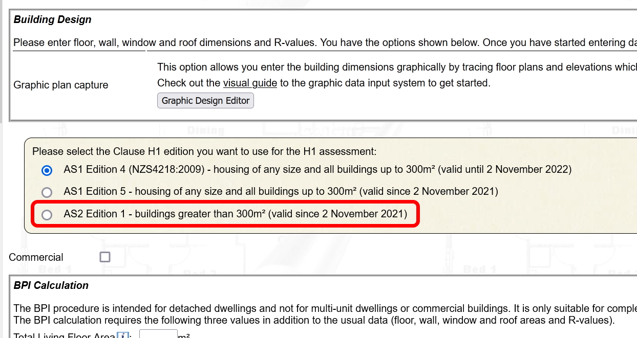
Simply enter your data as usual and select the AS2 Edition 1 assessment option.

The Design Navigator assessment also includes the Lighting Power Density calculation. You can use that in case your lighting designer does not provide the compliance statement for the lighting.
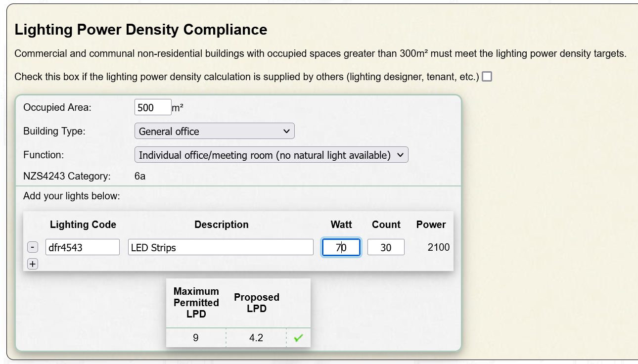
PS: I am also providing consultancy services to do H1 calculations for large commercial buildings. If you are interested you can send me the building plans to designnavigator@gmail.com and I can give you a quote.

Why is the online R-value different from the R-value calculated for a previous project?

You may have come across cases where an R-value has changed from the value that you previously calculated with the Design Navigator calculator.

There can be a few reasons for that:

  • It may simply be that I made a mistake in specifying the R-value for a certain material or insulation product. I obviously check the numbers and try my best to avoid this, but I am human, and errors do happen.
  • In other cases I may have simply updated a previous R-value when more accurate information became available. For example I may have used a default value from the literature but some new research has come up with more accurate values. Usually these corrections are fairly small and are less than R-0.05, but depending on the material and where in the consruction assembly it is used the differences can be larger. I usually use fairly conservative (low) default R-values when no specific information is available. So in general these corrections would lead to improved R-values in later versions of the calculator.
  • There are also instances where insulation manufactures or suppliers provide updated data on their products. This may be because they changed their manufacturing process or for some other reasons why they had to adjust the R-values from their original literature.
  • In some rare instances I also change the way the construction R-values are calculated. The method that Design Navigator applies is always based on Clause H1 which generally refers to NZS4214:2006 for the methodology to calculate R-values. Although this Standard is usually quite prescriptive there are cases where it leaves some room for interpretation. One such example are assemblies with immediately adjacent insulation layers, such as for example a timber framed wall with an additional insulated counterbatten layer. In these instances I generally follow the most intuitive approach, but if that leads to some problematic scenarios which seem inconsistent with actual data measurements I update the methodology. This can sometimes lead to quite significant changes to the calculated construction R-value. I therefore make these changes only when there are compelling reasons to do so and only if there is scientific evidence showing that the alternative approach leads to results that are more in line with real measurements. I usually also announce it when these types of substantial changes happened.

Are the R-values automatically updated for existing projects?

Generally no.

When the Design Navigator program saves a project, it does not only save the selected detail name, but it also saves the corresponding R-values and also the other options that were avalable for that component. This makes it backward compatible. Assume for example that I change the name of a cladding product or remove it all together because it is no more on the market. If the calculations for your saved project would refer to the new Design Navigator version the calculation would crash because it couldn't find the product anymore. Therefore all the products that were available for your selected construction detail are saved and restored when you re-open the project.

The other reason is that it would be quite confusing if you would create an H1 report for a project, and when you open the project again some time later the new R-values - and possibly even compliance results - would be different from the ones in the report that you created earlier.

There can of course be cases where you want to use the new product or an updated R-value for that product. In that case you will have to create a new construction R-value. Then simply select the same details as for your old construction R-value calculation in your project. Because you created a new construction the program will in that case use the current product names, R-values and calculation methods.

Do I have to edge insulate the joint between an unconditioned attached garage and the rest of the house?

F.1.2.2 says:

That's a recommendation only, and not mandatory.

But there are a few implications on how to calculate the slab R-value:

  1. If there is no edge insulation around the external walls it won't make any sense to add edge insulation between the garage and the house. So without that internal edge insulation the slab R-value calculation is simple. The slab area excludes the garage and the perimeter length includes the external house perimeter and the garage/house joint length, but not the external garage perimeter.
  2. But if there is edge insulation around the rest of the house it gets a bit tricky. If you would place edge insulation around the external garage walls then it would be useless, unless you include the whole garage in the thermal envelope, i.e. insulate the garage walls and roofs as if they are part of the house. But if you don't want to include the garage in the thermal envelope the only way would be to add edge insulation between the garage and the house, as the Clause F.1.2.2 recommends. Then the R-value calculation is the same as in the first scenario, but this time with edge insulation.
  3. But what to do if you have edge insulation around the rest of the house but exclude the garage from the thermal envelope and have no edge insulation between the garage and the house? As you can see in the DesNav calculator there is only an option for having edge insulation or having no edge insulation. There is no option for having edge insulation only around 80% of the perimeter (assuming for example that the joint length between the house and the garage makes up 20% of the total perimeter.)
    1. Simple option: In that case you just calculate the R-value with no edge insulation. You would use the perimeter length including both the actual external house perimeter and the joint length between the garage and the house (but not the external garage perimeter). That R-value will be a bit smaller than the actual R-value, but that would be a simple practical approach.
    2. Accurate option: If you want to be more accurate you could calculate both the R-value for the “no edge insulation“ scenario as explained in the “simple option” (RNoIns) and calculate the R-value with edge insulation RIns using the same dimensions as in the simple option. Then you can calculate the “average” R-value. But R-value averages are not “normal” averages. You will have to use this formula:
      100% / (%PerIns/RIns + %PerNoIns/RNoIns)
      With:
      %PerIns the percentage of the insulated external house perimeter (80% for example) and
      %PerNoIns the percentage of the uninsulated garage joint (20% for example)
      If for example the edge-insulated slab R-value is R-1.65 and the edge-uninsulated slab R-value is R-1.4 then the average R-value would be 100/(80/1.65 + 20/1.4) = 1.59

R-Value Calculation for adjacent
Insulation Layers

NZS4214:2006 and the Isothermal Planes Method

The Design Navigator calculator calculates assembly construction R-values according to the method described in NZS4214:2006 as required in Clause H1 of the New Zealand Building Code.

The calculation assesses the overall construction R-value based on a series of layers of materials that are placed behind each other. If these layers are all homogenious the R-values of the individual layers can simply be added together. But if the assembly contains non-homogenious layers, such as a framing/insulation layer, then the calculations become more complex. NZS4214:2006 describes how to undertake these calculations.

The method in the Standard is generally referred to as the "isothermal planes" method. The term refers to the assumption that the planes between adjacent layers of material are always at a uniform temperature as indicated in the sketch below (Figure 1).
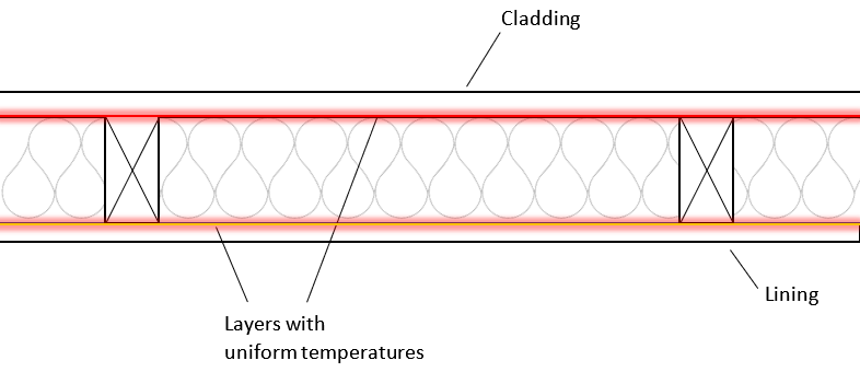
Fig.1 - Planes between assembly layers with a uniform temperature - isothermal planes assumption

This assumption is generally valid because most layers, such as the lining and the cladding in the example above, have low R-values. This means that heat will easily spread throughout the whole layer giving it a fairly uniform temperature. There are of course small temperature variations where the framing meets the lining and the cladding, but these variations can generally be ignored because of the small impact that these layers (lining and cladding) have on the overall construction R-value.

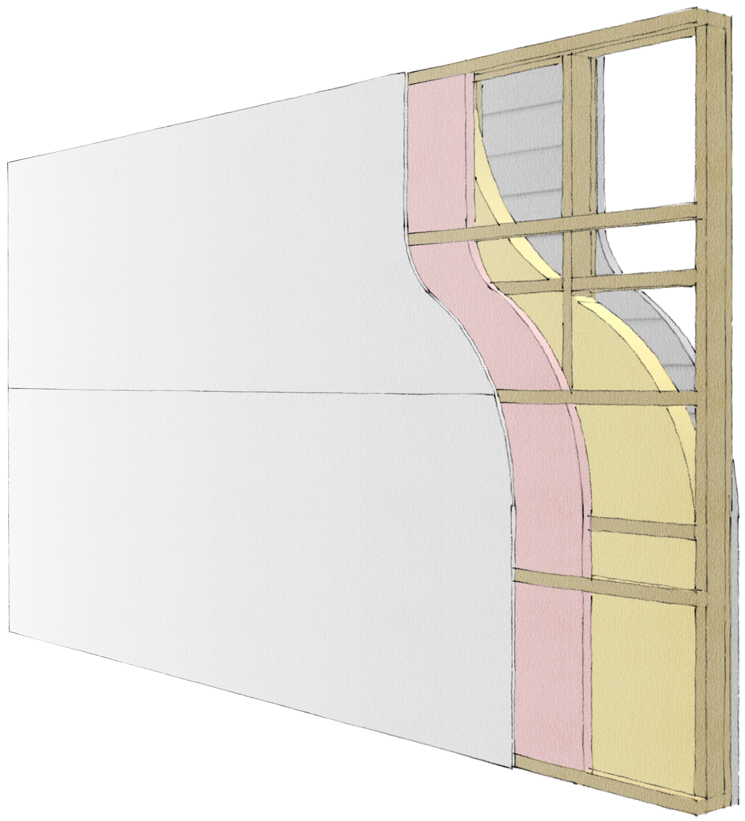
However, there are certain assemblies where this assumption is not correct and the impact on the assembly construction R-value becomes significant. Specifically where two insulation layers are in direct contact the temperature fluctuations that are caused by non-homogenious layers (such as the framing/insulation layer) will have a large impact on the construction R-value. The sketch in figure 2 illustrates this.
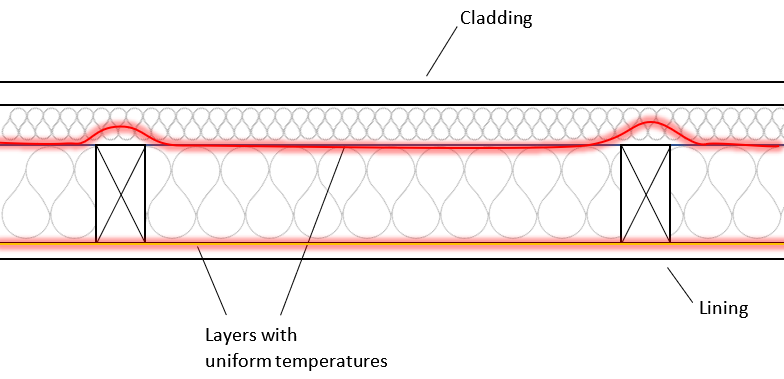
Fig.2 - In reality planes between assembly layers with a uniform temperature are distorted affecting the construction R-value

In this case the high R-value of the second insulation layer does not allow heat to disperse quickly across the layer. So the temperature in the plane between the original framing/insulation layer and that second insulation layer is not uniform. The reason why this has a larger effect on the overall construction R-value is that the layer containing these temperature disturbances is an insulation layer and therefore the influence on the overall R-value is more significant than in a lining or cladding layer which has a low R-values in the first place.

Why changing the Design Navigator Calculations

The isothermal planes method basically assumes that each layer is thermally isolated from the next, and therefore its R-value can be calculated without reference to any adjacent layers. But there are cases where this assumption does lead to obviously incorrect results. There are two such cases which you may have noticed at some stage already when using the Design Navigator R-value calculator:
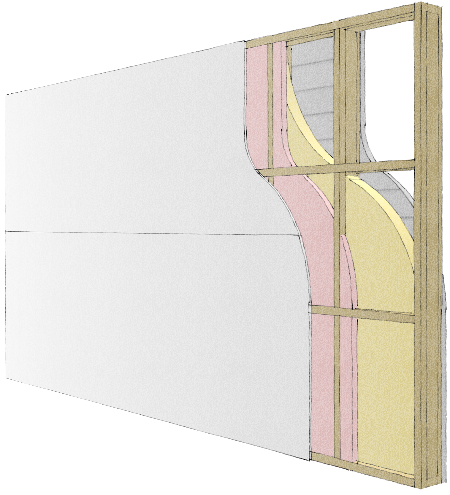
The upcoming changes of Clause H1 require much higher insulation levels. One practical solution are the addition of counter battens to wall and roof framing. This detail is therefore likely to become much more common and it is therefore important to have a more realistic calculation procedure for these "double insulation layer" details.

I have therefore updated the calculations for these types of scenarios. In simplified terms I have changed the calculations so that these double layers are being treated as one layer consisting of multiple sections with combinations of timber/timber, timber/insulation and insulation/insulation. By doing this the construction R-values of these details have improved and are more realistic.

Technical Justification for the new Method

This approach is valid and in line with the requirements of Clause H1 because NZS4214:2006 allows some flexibility in terms of how layers should be defined in the isothermal planes calculation method.

Item (a) in the instructions for isothermal planes calculations in NZS4214:2006 states that the two planes shall "enclose" the portion of the structure including the thermal bridging. This can be interpreted as meaning that multiple adjacent layers with thermal bridging can either be treated as separate bridged layers or as one combined bridged layer.
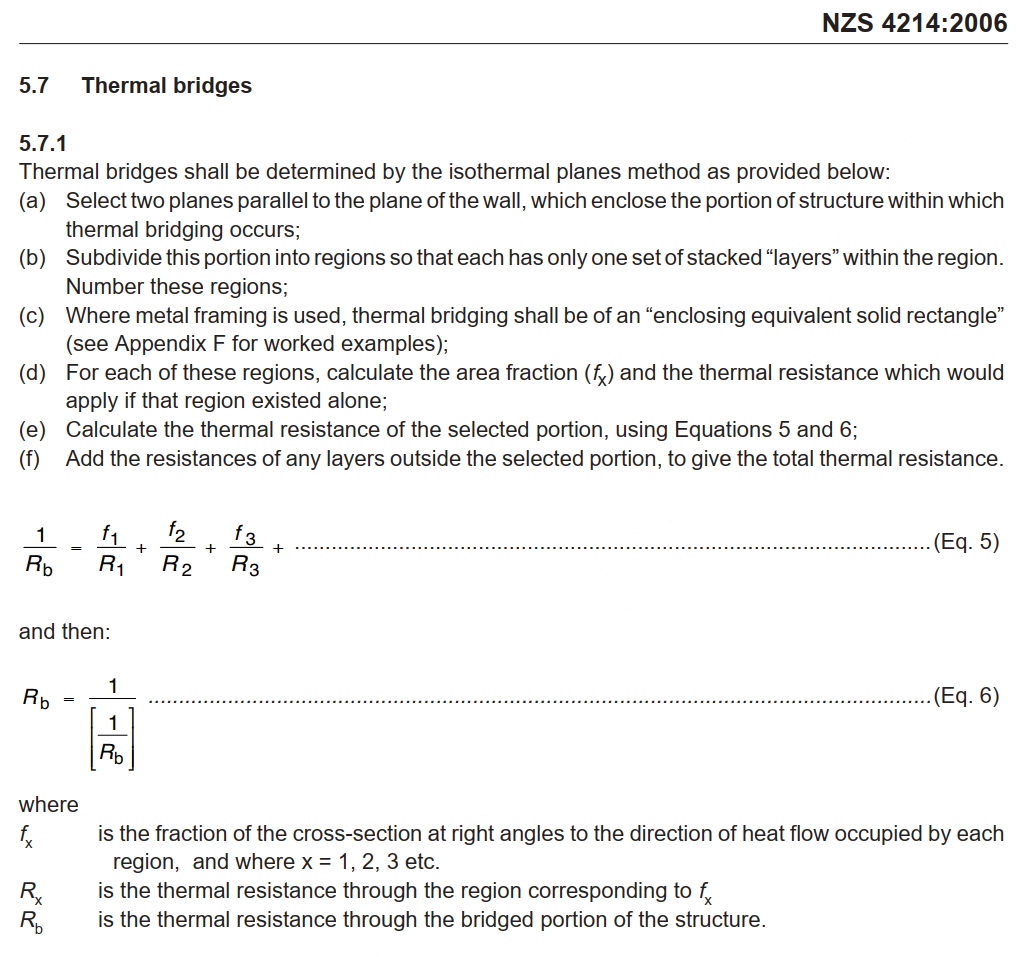
Fig.5 - NZS4214:2006 instructions for isothermal planes calculations

Research conducted by BRANZ and published in a paper at the ASHRAE Annual Conference in 1995 shows that this modified isothermal planes method has an excellent correlation with a large variety of construction details that were measured in the lab. Although this paper is several decades old no other reseach has shown since that there is a more accurate approach to achieve better correlations with measured data. (Harry Trethowen, SD-95-05-1 -- Validating the Isothermal Planes Method for R-Value Predictions, Symposium, ASHRAE Trans. 1995, Vol.101, Part 2).

How this affects your R-values

The changed approach to calculating these double insulation layers will increase the R-value of the assembly compared to the previous calculation method and be more in line with real measurement results.

This modified calculation is only applied to Design Navigator R-value calculations conducted from now on. If you calculated an R-value for a double insulation layer detail previously the old method is applied since the underlying format of the data that you entered at that time is preserved in your saved projects. If you want to update an old value please create a new construction detail with identical details.

Payment FAQs